Friday, May 14, 2010

The Potomac Project

No, this isn't some CIA mission to secure the nation's capital, it's my attempt to create the illusion of a WM Potomac 4-8-4 using a Bachmann Northern as the basis for a kitbash. I've got a million projects started in the train room, so I thought it would be a good time to start another one! I got a great deal on the engine from a guy over on Scale Rails Online that got it in a train set, but found it to be too big for his little layout. This is a reprise of a project I built for the WMRHS layout about 25 years ago, but the locomotive of course was a terrible runner, and I only did some modest cosmetics on the front end. I must have done something right, though, because someone thought enough of it to steal it.

Here's the beast we're going to try to create.


And here's the model we're starting with:


It's the newest version with the smoother drive and blackened hardware. The shell, on the other hand, is the same old same old that's been produced since the late 60's, replete with cast on everything, and a rectangular boiler profile below the belt line. I'm going to see how these problems might be fixed.


The first step is to lose the oil bunker. I had picked up an old Rivarossi Berkshire tender in anticipation of this project last year. I went ahead and painted the top of the tender Oxide Red, but left it there. I'll need to have some decals made to properly finish it.


I've prepped the tender to handle DCC, adding wipers to the trucks, and cutting down the frame to make room for the decoder. There looks to be room for a sound chip and a speaker, which I might add down the road.


The drive looks to be pretty easy to convert, with friction tabs being the only connection between the motor and the frame. These can be easily insulated to allow for separate connections to the decoder. I'll need to dig a trench up the spine of the frame to get the lighting wires installed, but that shouldn't be a big deal.

The other modification I made was to the drawbar on the tender. I had to cut it back a bit, and drill some new holes to bring the spacing between the engine and tender to a more realistic dimension.


I drilled two holes in the metal Rivarossi drawbar to be able to adjust the coupling distance. The shorter hole turned out to work fine with the 15" minimum main line curve on the layout, so that will be the permanent setting when I get to that point.


After drilling out the draw bar, I fabricated a new pin from a bit of sprue left over from a pack of MT 1015 couplers. I trimmed off the smaller arms, and filed the shaft smooth. It fits snugly into the hole left by the stock pin, with the drawbar resting on the tab that I left in place. Once the painting and other body work is done, I'll use a soldering pencil to melt a "rivet" on the top of the pin to secure it permanently to the engine.


Here's the engineer's side renovation plan. I want to get brass overlays etched to simulate the all-weather cab, and I'll have to rework the walk board into a single level from front to back. The ladders will also have to be modified, and I want to add new separately applied grabs down the length of the boiler. On the front of the smoke box, I'll need to relocate the headlight to the top of the box, and move the bell over to the right. The rest of the modifications will be on the pilot, similar to the 2-8-0 with the addition of a Z scale 905 coupler and a plow, plus a few other details.

The next step will be wiring in the decoder... as soon as I can get my hands on one!

See you next time.

Monday, May 10, 2010

Keeping it Real: The Thoughts Behind the Models

This topic came up on the Model Railroader Forum, and I thought it would be useful to cross post here. It pretty well sums up my general philosophy toward model railroading.

What tips and scene-composition / layout-composition techniques could you contribute to someone who is just beginning to learn about the concepts?
1. Observe nature (and pictures of nature). All of your questions about color, texture, juxtaposition, road numbers, locomotive details, weathering patterns and other modeling content can pretty much be answered with a short trip to the local rail line, or a quick google image search of your topic.


2. Don't hide behind "There's a Prototype for Everything" 
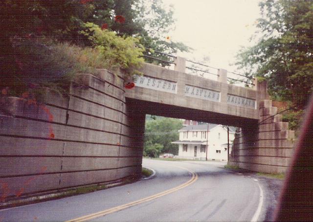
Yes, there probably is. However, it is in modeling the mundane, day to day reality that makes our modeling look more realistic.

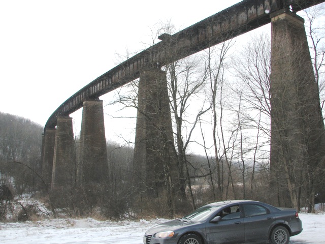
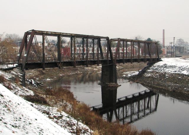
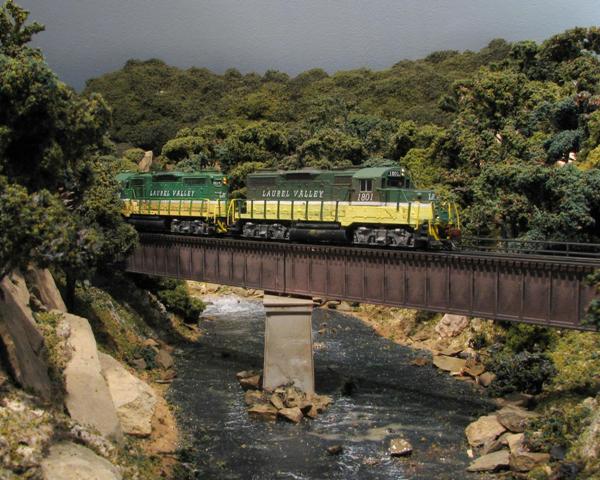
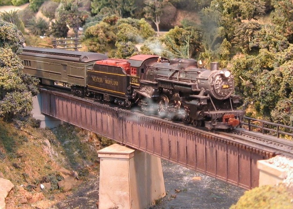
While this bridge is certainly spectacular, this next one might look a little more appropriate on your 4x8...

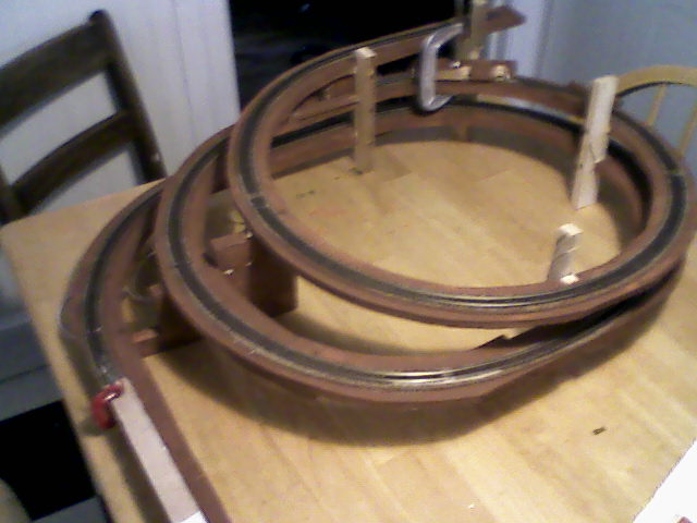
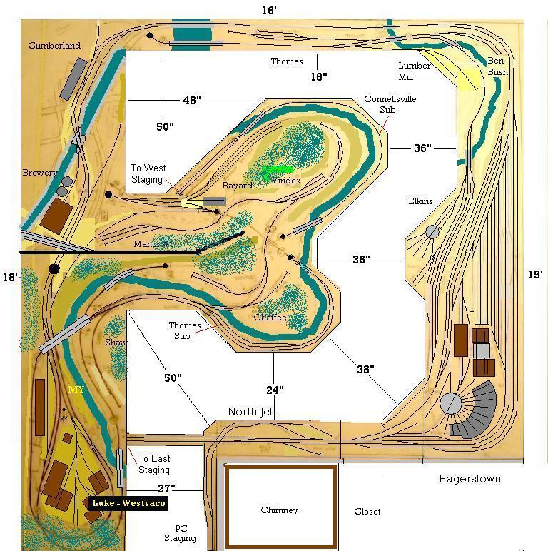
3. Try to visualize your scenery WHILE you're designing your track plan. Too often we get the tracks to do what we want them to do, but we leave too little room to create a realistic scene. This leads to multiple passes through the same scene, turns that are too tight, industries that look too small to warrant rail service, and a whole other myriad of sins. I'm certainly guilty of this one myself.

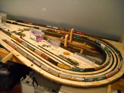
While I'm generally able to disguise these things in my photography, actually operating in these situations can be a challenge...

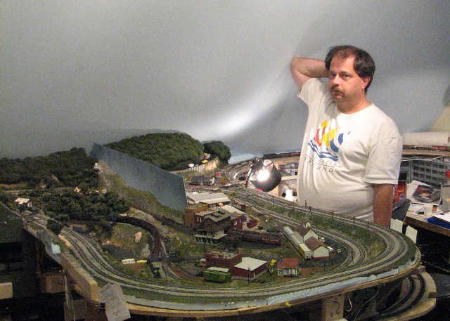
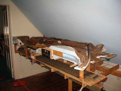
FYI, the peninsula in the foreground is currently undergoing a significant reconstruction to solve the problems created by the original track plan.
4. Don't be afraid of a little "Theater". In the end, you're building a model railroad. As such, the logical stars of the show are your trains. The supporting cast would be the scenery elements that are served by those trains. This is where your focus should be. I frequently read questions such as "What is the appropriate radius of a highway exit ramp?" or "How many parking spaces per square foot of retail space in Tuscaloosa, Alabama?" or some other such minutae that is totally irrelevant to the model railroad. To dwell on these ancillary details will leave you with a layout that might be technically perfect, but in the end is stark and odd looking. The more important questions would be, "How much of that exit ramp will be seen from the viewing angle that highlights the railroad?" and therefore, how much of that exit ramp do you really need to model? Or, "I've got a 6" x 12" area where I'd like to include a parking lot, how can I lay it out so it looks like a busy parking lot from the railroad? Or, what view blocks and details can I include to suggest a larger lot than I actually have room for?"

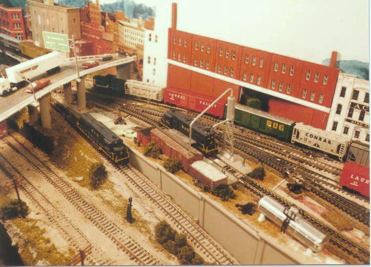
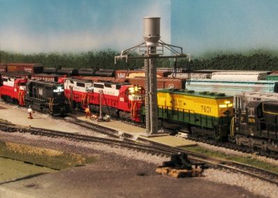
This scene was about 12" deep, but using the 3-D flats and 2D images on the back drop, some changes in elevation, and the highway bridge, which tapers from wide to narrow as it approaches the wall, create the illusion of a much larger scene. All of those background elements merely provide a stage for the trains to run through, so whether or not everything is perfectly in scale is immaterial.
Viewing angle is the key to what is and isn't important. It's okay to pinch a roadway down to nothing behind a clump of trees if you're never going to see that from a typical viewing angle.

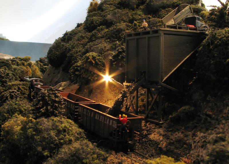
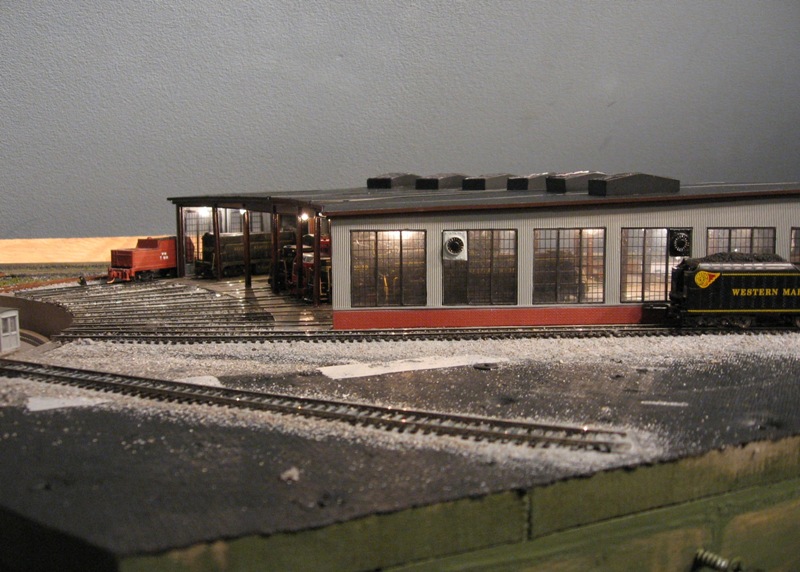
5. Sweat the Details that Matter
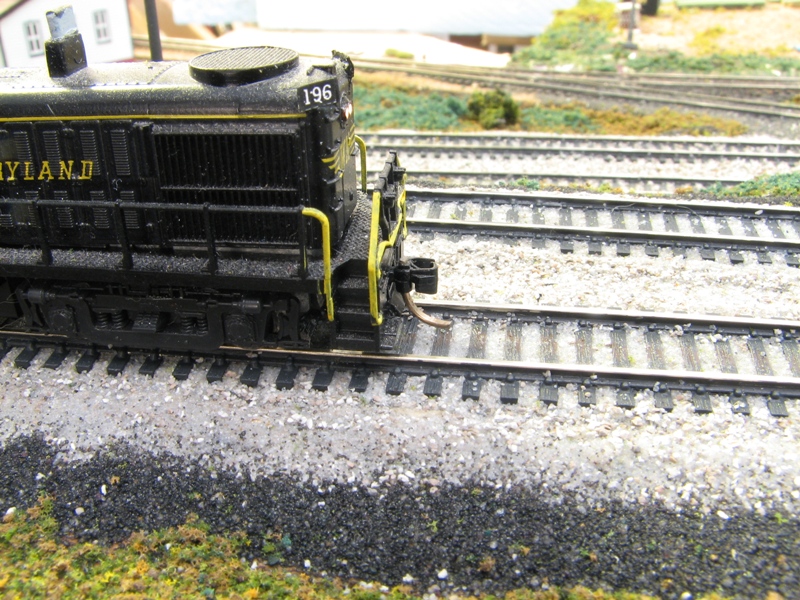
. This is the corollary to No. 4. While there are some things that just fade to the back ground (and should), there are others that demand, and when done properly, command your attention. Elements that contribute to the realism of the railroad itself. The track infrastructure is one element that I believe makes or breaks a layout's appearance. Unballasted snap track ain't going to cut it in my world. Nor will any of the pre-fab track systems with the big plastic roadbed already attached. I know there's a lot of folks that swear by the stuff, but as I stated previously, I'm very visually oriented, and there's just too many compromises for me to use that stuff.

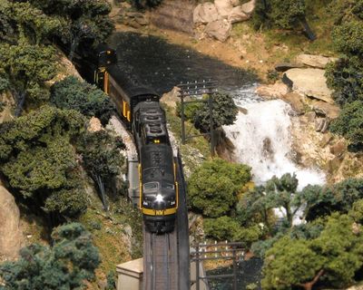
Same with bridges. It doesn't take much effort to look closely at a prototype to figure out what proper support looks like, or to determine what type of bridge is appropriate for a particular location. I covered this in a previous post.
Railroad-oriented structures should also carry their own weight. Again, this doesn't mean you need to model brick for brick or inch for inch to scale. But you should strive for a level of detail that exceeds the general level of the layout. After all, this is where the drama of your railroad is played out.


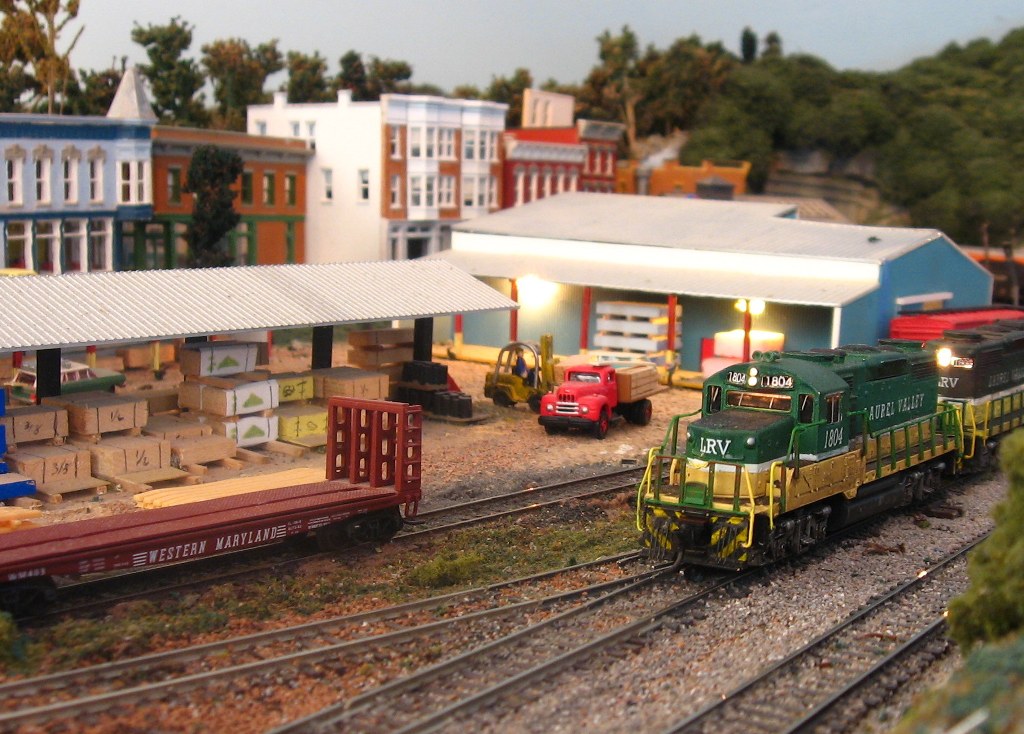
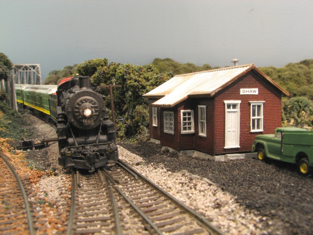
It doesn't require an "over the top" approach, either. Of course, an urban setting will require more attention than the more rural scenes above, bet even there, it's important leave some room for "nothing" between the focal points.


Finally,
6. Find a Theme and Follow it with Gusto! Building a layout is not a project that provides instant gratification. In fact, it can take years and years of work, usually being woven in and out of the other activities of life. Our interest can vary from fleeting moments dedicated to quick projects like weathering a few freight cars, to intense periods of major construction of benchwork, or installation of a new wiring system or signals. Given this long term commitment, we often find our interests drifting in and out of focus.
There are a lot of guys out there for whom this isn't an issue. Their main interest is in modeling passenger trains, so they are perfectly content to have the Broadway Limited pulled by a GG-1 running around the same track plan as the Empire Builder. That's fine, and serves the modeler's purpose. But unless the layout is based around a major terminal hub, it's hard for the casual viewer to fully appreciate the collection. Rod Stewart's urban terminal layout comes to mind. In the article, Rod confesses to being a passenger train fan, and makes no apologies for the eclectic collection he runs. But the setting in the big, busy city quickly conveys to a visitor the joy he finds in running the trains.
For others, a theme might be established following a particular prototypical line, or maybe a fictional route of an actual railroad. Others may dream up a free-lanced railroad that combines favorite elements of a few railroads, or just expresses an interest in a particular type of traffic in a particular region, like an Appalachian coal road, or a Midwestern grainger.

So there aren't any hard and fast rules about HOW to follow a theme, or even what theme to follow. But as a general principal, it's a good idea to have something in mind to guide your track planning, scenery choices, and rolling stock purchases.
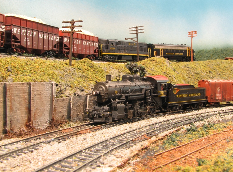
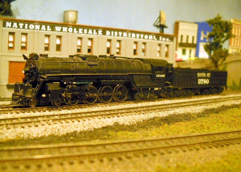
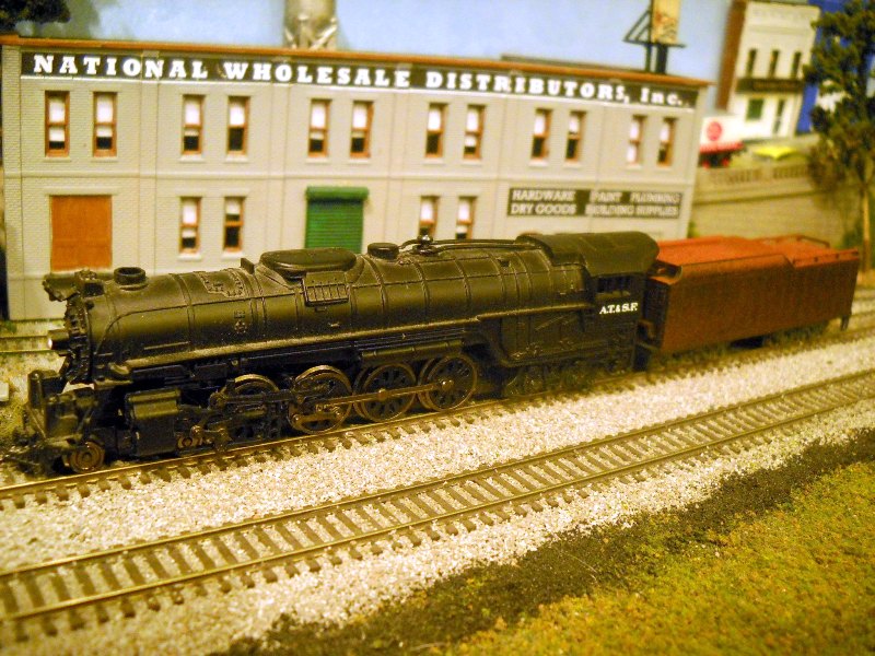
You'll also find that as you drill deeper into your chosen theme, there's all kinds of subtle details you can add that enhance the realism of your layout. On my Western Maryland themed layout, I started with an idea of what parts of the operation I wanted to emulate, what types of rolling stock I would need, and the kinds of engines I would want to run.

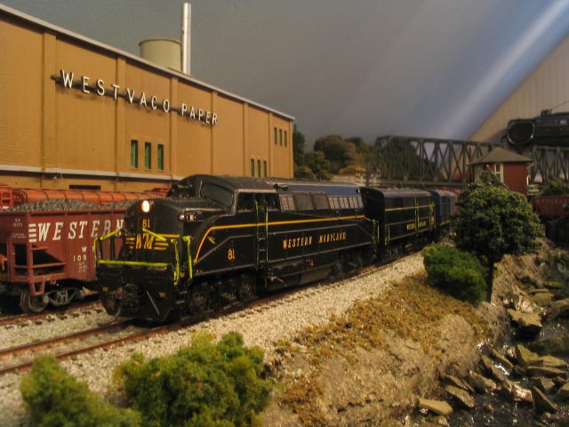
From there, I started learning more about the railroad's architecture, traffic patterns, interchanges, and other details I never imagined. I was able to take this newly gained knowledge and come up with projects that would help really cement the time and place of my layout.


To sum up, don't be afraid to push the boundaries of your comfort zone. If what you built was really good, look at it again, and see what it would take to make it really great! There's a tremendous amount of pleasure to be gained from learning a new skill, or trying something different. If you're content where you are, well, that's fine. But if you see other layouts that really strike a chord with you, get busy! Start small, work on a small corner of your layout and finish it. Move on to the next section, and see if you can do better than you did on the first section.
You can create a scene that has a powerful visual impact, defines your locale and era, and impresses the operator, casual visitor, and photographer...

Now get to work!
Lee

Thursday, May 6, 2010

Begin at the End: The Line to Elkins


It is said that the journey of a thousand miles begins with a single step. For my expansion/reconstruction project, the first step was to build what will ultimately be the most remote part of the railroad, a small yard representing Elkins, West Virginia.

The yard is located on this rather austere looking shelf, which is composed of a 12" wide hollow core door (graciously donated to the cause by Dave Foxx) that is cut back to about 4'8" long. Since my new plan involves some considerable grade changing acrobatics, I wanted to make sure I knew where the highest elevation point would be, and this would be it. The Elkins yard deck sits at 50" above the floor, about a foot higher than the main level.

The real Elkins was a compact yard by most railroad standards, even when compared to other WM facilities at Knobmount or Hagerstown, but it was still too big to model comprehensively in the space I have available. In addition to the yard functions, Elkins also hosted the WM's primary car shops, caboose shops, and a 17-stall roundhouse. My original plan hoped to include tracks to represent many of these functions, but the re-draw forced me to do away with most of it. Now, Elkins is represented with a simple five track stub yard, a two stall engine house, and an Arrival/Departure track that will adequately launch trains of roughly 20 cars.


To attain this level of elevation, I needed to devise a simple three-turn helix, which was made not-so-simple by the fact that the layout resides in my attic. As such, I had more room for the bottom turn than the top! Since the Thomas Sub to Elkins on the real WM was a twisting, steep railroad, equipment was limited to short wheelbase locomotives, and relatively small cars, I was content to make the helix of a relatively tight radius and steep grade. The WM's fleet of 34' 55-ton hoppers survived well into the 1970's due to this geography, as did its relatively ancient stable of RS-3's and F-7's.

The top turn has a track center diameter of roughly 24". The middle is an oval, 24" x 27", and the bottom rounds out at 24" x 30". The ever widening dimension tucks back under the sloped ceiling.


(Pardon the blurry image... I shot this with a camera whose manual has thus far evaded my eyes). To connect the two pieces, the yard and the helix, I built two narrow shelf modules to cross the window that occupies the center of the room's main vertical wall... These comprise the long passing siding that serves as the A/D tracks. I've included a crossover in the middle of the siding, which adds a bit of flexibility when setting up outbound trains, and juggling switching duties with an incoming drag of empties.

The siding is... or rather will be... controlled from this small panel that I stuck into a highway embankment.


The switches at the east and west end of Kerens are operated by yet-to-be-wired Tortoise switch machines, while the yard entrance and the west end of Elkins are manual. There are a quite a few steps to take before this work is connected to the main layout, primarily the relocation of my workbench to the other side of the room. Once that's done, I can construct the benchwork for Cumberland, which will in turn permanently support the Thomas Sub helix. Until then, I can goof around setting up trains and running them in and out of the yard.

Simple things for simple minds!

Wednesday, May 5, 2010

Staging: The Alpha and the Omega of a Model Railroad.


Back in February, two of my regular crew braved the threat (and ultimately the onset) of a blizzard, and came down to help me construct and install the base for the first phase of the expansion project. It consisted of a large staging yard, configured as a "balloon" track, which basically forms a reverse loop so trains that exit the modeled part of the railroad can return from the same direction. This is the biggest improvement I'm making to the layout, and actually is the driving force behind many of the other changes.

The operating schematic of the railroad is basically an extended "X" shape. The two legs to the east are represented by a single staging yard, while the two legs to the west are divided into two separate routes. The northerly route suggests the WM's Connellsville Sub, extending from Ridgeley Yard (my on-scene working yard) to Connellsville, PA, represented by the new staging loop. The southerly route represents the Thomas Sub, which originated most of the coal hauled by the WM. This route also extends from Ridgeley, then splits from the main at Maryland Junction, then on to Elkins, West Virginia. Elkins is represented by a small active yard where operators will be kept busy marshalling coal loads for various destinations in the east and midwest.

Anyway, one of the key objectives of this project was to improve the staging I had available. I had included eight through tracks in the original plan, and even built it out, but this quickly proved to be an issue. First, eastbound trains would leave the layout going east to destinations such as Baltimore or Lurgan, but in the original plan, they would arrive back on the layout at the west end from originations like Pittsburgh, Toledo, or Chicago. Okay, that would be easy enough to fix by writing the car cards and waybills carefully. The problem became power swaps. The WM was notorious for its run-through agreements, and at Hagerstown on any given day, you could see engines from 5 or more different railroads. Even this isn't that bad, just mix it up, right?


Wrong. Reading Company power would come to Hagerstown from the east, then go back to the east. N&W engines would come in from the west, and either go back the way it came, or switch over and head south on the Shenandoah Valley line to Roanoke. B&O power would arrive from Cherry Run, west of Hagerstown, but wouldn't show up on WM rails west of there. So you see the dilemma. I couldn't very well have a train with Reading power appear on the layout at Connellsville, nor would a Norfolk and Western unit grace the rails east of the yard. Balloon staging solves this. What goes east, comes back from the east, and likewise to and from the west. It also makes writing waybills a lot more logical.

The biggest advantage to the new configuration will be the huge increase in capacity the railroad will now enjoy. Before I had eight staging tracks, with an average capacity of 16 car trains. Now I'll have upwards of 20 staging tracks, with the through tracks able to handle 30 cars or more. This means I can schedule more trains that are longer, and cover more destinations. It also means I have to expand the capacity of the active yard to handle more and longer cuts of cars bound for a broader range of destinations. Working on improving the yard at Ridgeley will be a whole other topic!

But enough about me. If you don't think you need staging to enjoy your railroad more, I'm going to politely suggest that you're dead wrong. Even the smallest roundy roundy can benefit from a switch and a few tracks off to the side that provide a place for traffic to come from and then go to. A simple shelf switching layout is really dead in the water unless you can push the outbound cars "off stage" to make room for switching cars that are in the scene. It just makes your model trains work more like a model transportation system. Granted, my staging needs are a bit elaborate, but that's based on the traffic patterns supported by the railroad I model. But staging doesn't have to be.

So sharpen your pencil, and see if there's not a way to tuck a few sidings out of the way to give your trains someplace to go.

Tuesday, May 4, 2010

WM Westernlines 2.0


After 5 years or so of running the N Scale Western Maryland Western Lines layout in it's "temporary" configuration, it's finally time to start the process of building the new improved track plan. This seemed as good a time as any to open up a new blog to share the progress of the work as it happens.
For the past few years, I had an ongoing thread about the layout on Scale Rails Online, a model railroading forum that covers the broad spectrum of the hobby. Unfortunately, in the spring of 2010, the site was hacked, and all the layout progress blogs, including mine, got lost in the ether.
So here we are then.

To bring you up to speed, around 2001, I started designing a layout to fit in a spare room in my attic. The N scale plan was designed to represent the Western Maryland Railway's west end, from the major terminal at Hagerstown, Maryland, through Maryland Junction where the line splits with the main line continuing on to Connellsville, Pennsylvania, and the Thomas Sub branch to Elkins, West Virginia. In retrospect, the plan was a mess:


In a nutshell, some of the grades were unworkable, the staging was impractical, and the aisles were way too narrow. But I didn't know any of this at the time, so I plunged headlong into building the first major part of the layout, believing that I could work out the kinks as I went along. So off to the garage I went, and over the course of a year, I built the section in the lower left, including the Westvaco Paper mill at Luke. The construction process is covered here:


The basic frame came from a former layout, and I started with a staging yard, then added the upper, scenic level. Once this section reached a state of completion, and the room it was going in was ready to receive it, I recruited my neighbor Tom to help me load it up the steps.


Once this step was taken, I realized that I absolutely positively had to figure out a way to run trains. Thus, a temporary set of loops was built to close up a circuit. Well, one thing led to another, and soon I had scabbed together some scenery, a connecting line that tied the paper mill scene to the staging yard below it, as well as a working yard and engine terminal... all of it temporary. This little slide show covers much of the temporary sections, including the paper mill scene:


It all seemed to work pretty well, so I began hosting some operation sessions, inviting some members of the Railwire Forum community to try it out. We had a lot of fun with it, and that led me to prepare an article for publication in N Scale Magazine. This appeared in the September/October 2009 edition.

Despite the fun we had, the operating sessions revealed some serious problems with the temporary track plan, and also raised some concerns about how the original track plan would work, particularly in regards to staging. So, in 2009, I began working on a major revision of the plan to address these problems. And that's where we are now. The new track plan is posted on the layout website. I've changed the staging to "balloon" style tracks at the east and west ends, I moved Elkins to an upper level away from the Ridgeley Yard, and added a couple of helixes to add some operating distance, and help with the grade separations. There's still a few kinks I'll need to work out, but I think I solved most of the operational problems.

In future posts I'll be featuring the deconstruction of the temporary loops, and the re-construction of the yard, engine terminal and the peninsula where it all will come together.

Stay tuned for future developments!